
How AI Is Transforming Daily Work in Service Teams
Reduce downtime and improve service efficiency with AI-powered troubleshooting. Learn how service teams use ilean to solve problems faster and capture knowledge.
Esri ASCII raster files (*.asc) are commonly used to store digital terrain models, such as LiDAR data. In the following lines, we will explain how the information is arranged in this file format and we will describe a workflow to create a Civil 3D surface from an ASC file.
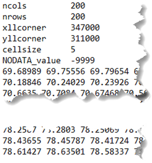
In the context of digital terrain models, an esri ASCII raster file contains the elevation of a number of square cells that form a grid. If you open it using a text editor, such as notepad, you can see the data that makes up the file. It starts with a header that defines the properties of the grid followed by the data, with the elevation of the grid cells separated by spaces.
The following is a list of the parameters that are part of the header:
The data that follows is a list of elevations, separated by spaces, sorted from top to bottom and left to right. That is, the first value is the elevation of the upper left cell, followed by the elevation of the second leftmost cell from the top row and so on. Typically, the values are arranged in separate lines corresponding to the different rows, with the first line representing the row at the top of the raster. However, carriage returns are not necessary at the end of each row as the number of columns determines when the next row begins.
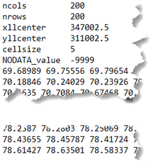
The following two examples show the same raster grid, using the coordinates of the corner or the centre of the origin cell.
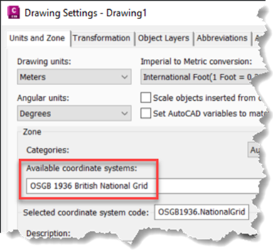
Before creating a surface from an ASC file in Civil 3D, we need to check that the coordinate system is set correctly. It can be set from ‘Edit Drawing Settings…’, as shown below.

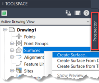
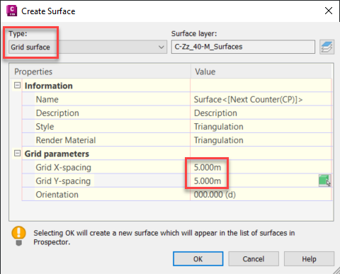
We then start by creating a new surface.
For points that lie in a regular grid, it is advised to use a grid surface rather than a TIN or triangulation surface. A grid surface will require less disk space than a TIN surface, leading to quicker load times, especially if the number of points is high.
Grid X-spacing and grid Y-spacing should be set to the ‘cellsize’ parameter from the header of the ASC file.
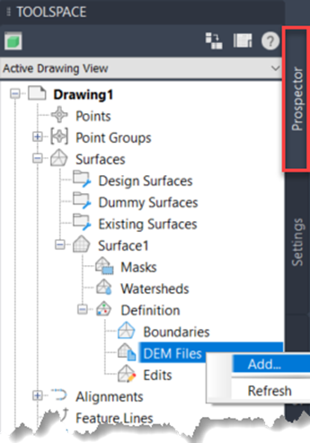
From prospector, look for the surface and add the DEM file from the ‘Definition’ branch.
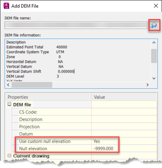
Browse to the ASC file and set ‘Use custom null elevation’ to ‘Yes’ if the ‘NODATA_value’ parameter is part of the header in the ASC file. In that case, ‘Null elevation’ should be set to the ‘NODATA_value’ parameter. If that number is found in the file, it will be ignored and no point will be created for that particular grid cell.
If you don’t use a custom null elevation, it will create a point at that level (-9999m in our example), which is incorrect.
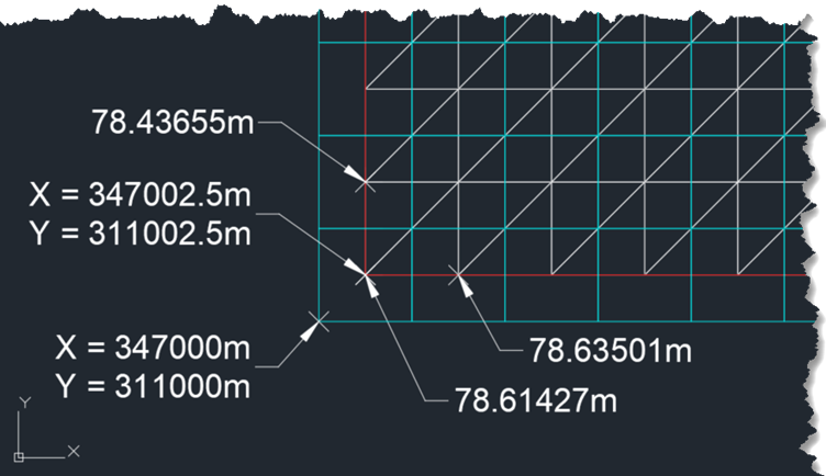
After confirming the previous dialog, the surface will be generated.

A point will be created at the centre of each grid cell. In the image below, the grid from the ASC file is shown in cyan, the boundary of the surface in red, and the surface triangles in white. The coordinates and levels that have been labelled can be found in the example files that we showed at the start of the article.
Reduce downtime and improve service efficiency with AI-powered troubleshooting. Learn how service teams use ilean to solve problems faster and capture knowledge.

Cybersecurity risks are not always caused by sophisticated attacks or major system failures. In many cases, risk builds quietly through everyday habits, overlooked processes, and limited visibility into where data is stored or how users interact with systems.

Learn how to reduce cyber risk through stronger security foundations. This month's bulletin covers home office security, legacy technology risks, vulnerability management, MFA, and cybersecurity best practices.